1. CHARACTERISTICS OF MAP PROJECTIONS #
The general purpose of map projections and the basic problems encountered have been discussed often and well in various books on cartography and map projections. (Robinson, Sale, Morrison, and Muehrcke, 1984; Steers, 1970; and Greenhood, 1964, are among later editions of earlier standard references.) Every map user and maker should have a basic understanding of projections, no matter how much computers seem to have automated the operations. The concepts will be concisely described here, although there are some interpretations and formulas that appear to be unique.
For almost 500 years, it has been conclusively established that the Earth is essentially a sphere, although a number of intellectuals nearly 2,000 years earlier were convinced of this. Even to the scholars who considered the Earth flat, the skies appeared hemispherical, however. It was established at an early date that attempts to prepare a flat map of a surface curving in all directions leads to distortion of one form or another.
A map projection is a systematic representation of all or part of the surface of a round body, especially the Earth, on a plane. This usually includes lines delineating meridians and parallels, as required by some definitions of a map projection, but it may not, depending on the purpose of the map. A projection is required in any case. Since this cannot be done without distortion, the cartographer must choose the characteristic which is to be shown accurately at the expense of others, or a compromise of several characteristics. If the map covers a continent or the Earth, distortion will be visually apparent. If the region is the size of a small town, distortion may be barely measurable using many projections, but it can still be serious with other projections. There is literally an infinite number of map projections that can be devised, and several hundred have been published, most of which are rarely used novelties. Most projections may be infinitely varied by choosing different points on the Earth as the center or as a starting point. It cannot be said that there is one “best” projection for mapping. It is even risky to claim that one has found the “best” projection for a given application, unless the parameters chosen are artificially constricting. A carefully constructed globe is not the best map for most applications because its scale is by necessity too small. A globe is awkward to use in general, and a straightedge cannot be satisfactorily used on one for measurement of distance.
The details of projections discussed in this book are based on perfect plotting onto completely stable media. In practice, of course, this cannot be achieved. The cartographer may have made small errors, especially in hand-drawn maps, hut a more serious problem results from the fact that maps are commonly plotted and printed on paper, which is dimensionally unstable. Typical map paper can expand over 1 percent with a 60 percent increase in atmospheric humidity, and the expansion coefficient varies considerably in different directions on the same sheet. This is much greater than the variation between common projections on large scale quadrangles, for example. The use of stable plastic bases for maps is recommended for precision work, but this is not always feasible, and source maps may be available only on paper, frequently folded as well. On large-scale maps, such as topographic quadrangles, measurement on paper maps is facilitated with rectangular grid overprints, which expand with the paper. Grids are discussed later in this book.
The characteristics normally considered in choosing a map projection are as follows:
Area - Many map projections are designed to be equal-area, so that a coin of any size, for example, on one part of the map covers exactly the same area of the actual Earth as the same coin on any other part of the map. Shapes, angles, and scale must be distorted on most parts of such a map, but there are usually some parts of an equal-area map which are designed to retain these characteristics correctly, or very nearly so. Less common terms used for equal-area projections are equivalent, homolographic, or homalographic (from the Greek homalos or homos (“same”) and graphos (“write”)); authalic (from the Greek autos (“same”) and ailos (“area”)), and equiareal.
Shape - Many of the most common and most important projections are conformal or orthomorphic (from the Greek orthos or “straight” and morphe or “shape”), in that normally the relative local angles about every point on the map are shown correctly. (On a conformal map of the entire Earth there are usually one or more “singular” points at which local angles are still distorted.) Although a large area must still be shown distorted in shape, its small features are shaped essentially correctly. Conformality applies on a point or infinitesimal basis, whereas an equal-area map projection shows areas correctly on a finite, in fact mapwide basis. An important result of conformality is that the local scale in every direction around any one point is constant. Because local angles are correct, meridians intersect parallels at right (90°) angles on a conformal projection, just as they do on the Earth. Areas are generally enlarged or reduced throughout the map, but they are correct along certain lines, depending on the projection. Nearly all large-scale maps of the Geological Survey and other mapping agencies throughout the world are now prepared on a conformal projection. No map can be both equal-area and conformal.
While some have used the term aphylactic for all projections which are neither equal-area nor conformal (Lee, 1944), other terms have commonly been used to describe special characteristics:
Scale - No map projection shows scale correctly throughout the map, but there are usually one or more lines on the map along which the scale remains true. By choosing the locations of these lines properly, the scale errors elsewhere may be minimized, although some errors may still be large, depending on the size of the area being mapped and the projection. Some projections show true scale between one or two points and every other point on the map, or along every meridian. They are called equidistant projections.
Direction - While conformal maps give the relative local directions correctly at any given point, there is one frequently used group of map projections, called azimuthal (or zenithal), on which the directions or azimuths of all points on the map are shown correctly with respect to the center. One of these projections is also equal-area, another is conformal, and another is equidistant. There are also projections on which directions from two points are correct, or on which directions from all points to one or two selected points are correct, but these are rarely used.
Special characteristics - Several map projections provide special characteristics that no other projection provides. On the Mercator projection, all rhumb lines, or lines of constant direction, are shown as straight lines. On the Gnomonic projection, all great circle paths-the shortest routes between points on a sphere shown as straight lines. On the Stereographic, all small circles, as well as great circles, are shown as circles on the map. Some newer projections are specially designed for satellite mapping. Less useful but mathematically intriguing projections have been designed to fit the sphere conformally into a square, an ellipse, a triangle, or some other geometric figure.
Method of construction - In the days before ready access to computers and plotters, ease of construction was of greater importance. With the advent of computers and even pocket calculators, very complicated formulas can be handled almost as routinely as simple projections in the past.
While the above six characteristics should ordinarily be considered in choosing a map projection, they are not so obvious in recognizing a projection. In fact, if the region shown on a map is not much larger than the United States, for example, even a trained eye cannot often distinguish whether the map is equal-area or conformal. It is necessary to make measurements to detect small differences in spacing or location of meridians and parallels, or to make other tests. The type of construction of the map projection is more easily recognized with experience, if the projection falls into one of the common categories.
There are three types of developable1 surfaces onto which most of the map projections used by the USGS are at least partially geometrically projected. They are the cylinder, the cone, and the plane. Actually all three are variations of the cone. A cylinder is a limiting form of a cone with an increasingly sharp point or apex. As the cone becomes flatter, its limit is a plane. If a cylinder is wrapped around the globe representing the Earth (see fig. 1), so that its surface touches the Equator throughout its circumference, the meridians of longitude may be projected onto the cylinder as equidistant straight lines perpendicular to the Equator, and the parallels of latitude marked as lines parallel to the Equator, around the circumference of the cylinder and mathematically spaced for certain characteristics. For some cases, the parallels may also be projected geometrically from a common point onto the cylinder, but in the most common cases they are not perspective. When the cylinder is cut along some meridian and unrolled, a cylindrical projection with straight meridians and straight parallels results. The Mercator projection is the best-known example, and its parallels must be mathematically spaced.
If a cone is placed over the globe, with its peak or apex along the polar axis of the Earth and with the surface of the cone touching the globe along some particular parallel of latitude, a conic (or conical) projection can be produced. This time the meridians are projected onto the cone as equidistant straight lines radiating from the apex, and the parallels are marked as lines around the circumference of the cone in planes perpendicular to the Earth’s axis, spaced for the desired characteristics. The parallels may not be projected geometrically for any useful conic projections. When the cone is cut along a meridian, unrolled, and laid flat, the meridians remain straight radiating lines, but the parallels are now circular arcs centered on the apex. The angles between meridians are shown smaller than the true angles.
A plane tangent to one of the Earth’s poles is the basis for polar azimuthal projections. In this case, the group of projections is named for the function, not the plane, since all common tangent-plane projections of the sphere are azimuthal. The meridians are projected as straight lines radiating from a point, but they are spaced at their true angles instead of the smaller angles of the conic projections. The parallels of latitude are complete circles, centered on the pole. On some important azimuthal projections, such as the Stereographic (for the sphere), the parallels are geometrically projected from a common point of perspective; on others, such as the Azimuthal Equidistant, they are nonperspective.
FIGURE 1.— Projection of the Earth onto the three major surfaces. In a few cases, projection is geometric, but in most cases the projection is mathematical to achieve certain features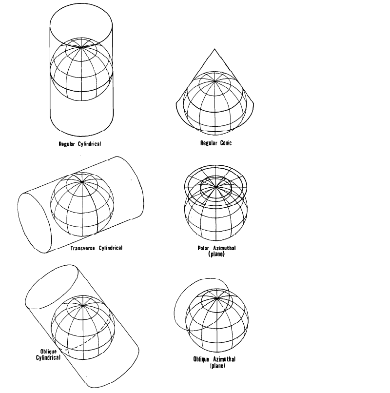
The concepts outlined above may be modified in two ways, which still provide cylindrical, conic, or azimuthal projections (although the azimuthals retain this property precisely only for the sphere).
The cylinder or cone may be secant to or cut the globe at two parallels instead of being tangent to just one. This conceptually provides two standard parallels; but for most conic projections this construction is not geometrically correct. The plane may likewise cut through the globe at any parallel instead of touching a pole, but this is only useful for the Stereographic and some other perspective projections.
The axis of the cylinder or cone can have a direction different from that of the Earth’s axis, while the plane may be tangent to a point other than a pole (fig. 1). This type of modification leads to important oblique, transverse, and equatorial projections, in which most meridians and parallels are no longer straight lines or arcs of circles. What were standard parallels in the normal orientation now become standard lines not following parallels of latitude.
Other projections resemble one or another of these categories only in some respects. There are numerous interesting pseudocylindrical (or “false cylindrical”) projections. They are so called because latitude lines are straight and parallel, and meridians are equally spaced, as on cylindrical projections, but all meridians except the central meridian are curved instead of straight. The Sinusoidal is a frequently used example. Pseudoconic projections have concentric circular arcs for parallels, like conics, but meridians are curved; the Bonne is the only common example. Pseudoazimuthal projections are very rare; the polar aspect has concentric circular arcs for parallels, and curved meridians. The Polyconic projection is projected onto cones tangent to each parallel of latitude, so the meridians are curved, not straight. Still others are more remotely related to cylindrical, conic, or azimuthal projections, if at all.
A developable surface is one that can be transformed to a plane without distortion. ↩︎