2. LATITUDE AND LONGITUDE #
To identify the location of points on the Earth, a graticule or network of longitude and latitude lines has been superimposed on the surface. They are commonly referred to as meridians and parallels, respectively. The concept of latitudes and longitudes was originated early in recorded history by Greek and Egyptian scientists, especially the Greek astronomer Hipparchus (2nd century, B.C.). Claudius Ptolemy further formalized the concept (Brown, 1949, p. 50, 52, 68).
PARALLELS OF LATITUDE #
Given the North and South Poles, which are approximately the ends of the axis about which the Earth rotates, and the Equator, an imaginary line halfway between the two poles, the parallels of latitude are formed by circles surrounding the Earth and in planes parallel with that of the Equator. If circles are drawn equally spaced along the surface of the sphere, with 90 spaces from the Equator to each pole, each space is called a degree of latitude. The circles are numbered from 0° at the Equator to 90° North and South at the respective poles. Each degree is subdivided into 60 minutes and each minute into 60 seconds of arc. For 2,000 years, measurement of latitude on the Earth involved one of two basic astronomical methods. The instruments and accuracy, but not the principle, were gradually improved. By day, the angular height of the Sun above the horizon was measured. By night, the angular height of stars, and especially the current pole star, was used. With appropriate angular conversions and adjustments for time of day and season, the latitude was obtained. The measuring instruments included devices known as the cross-staff, astrolabe, back-staff, quadrant, sextant, and octant, ultimately equipped with telescopes. They were supplemented with astronomical tables called almanacs, of increasing complication and accuracy. Finally, beginning in the 18th century, the use of triangulation in geodetic surveying meant that latitude on land could be determined with high precision by using the distance from other points of known latitude. Thus measurement of latitude, unlike that of longitude, was an evolutionary development almost throughout recorded history (Brown, 1949, p. 180-207).
MERIDIANS OF LONGITUDE #
Meridians of longitude are formed with a series of imaginary lines, all intersecting at both the North and South Poles, and crossing each parallel of latitude at right angles, but striking the Equator at various points. If the Equator is equally divided into 360 parts, and a meridian passes through each mark, 360 degrees of longitude result. These degrees are also divided into minutes and seconds. While the length of a degree of latitude is always the same on a sphere, the lengths of degrees of longitude vary with the latitude (see fig. 2). At the Equator on the sphere, they are the same length as the degree of latitude, but elsewhere they are shorter.
There is only one location for the Equator and poles which serve as references for counting degrees of latitude, but there is no natural origin from which to count degrees of longitude, since all meridians are identical in shape and size. It thus becomes necessary to choose arbitrarily one meridian as the starting point, or prime meridian. There have been many prime meridians in the course of history, swayed by national pride and international influence. For over 150 years, France officially used the meridian through Ferro, an island of the Canaries. Eighteenth- century maps of the American colonies often show longitude from London or Philadelphia. During the 19th century, boundaries of new States were described with longitudes west of a meridian through Washington, D.C., 77°03’ 02.3" west of the Greenwich (England) Prime Meridian (Van Zandt, 1976, p. 3). The latter was increasingly referenced, especially on sea charts due to the proliferation of those of British origin. In 1884, the International Meridian Conference, meeting in Washington, agreed to adopt the “meridian passing through the center of the transit instrument at the Observatory of Greenwich as the initial meridian for longitude,” resolving that “from this meridian longitude shall be counted in two directions up to 180 degrees, east longitude being plus and west longitude minus” (Brown, 1949, p. 283, 297). FIGURE 2.— Meridians and parallels on the sphere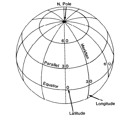
The choice of the prime meridian is arbitrary and may be stated in simple terms. The accurate measurement of the difference in longitude at sea between two points, however, was unattainable for centuries, even with a precision sufficient for the times. When extensive transatlantic exploration from Europe began with the voyages of Christopher Columbus in 1492, the inability to measure east-west distance led Lo numerous shipwrecks with substantial loss of lives and wealth. Seafaring nations beginning with Spain offered sizable rewards for the invention of satisfactory methods for measuring longitude. It finally became evident that a portable, dependable clock was needed, so that the height of the Sun or stars could be related to the time in order to determine longitude. The study of the pendulum by Galileo, the invention of the pendulum clock by Christian Huygens in 1656, and Robert Hooke’s studies of the use of springs in watches in the 1660’s provided the basic instrument, but it was not until John Harrison of England responded to his country’s substantial reward posted in 1714 that the problem was solved. For five decades, Harrison devised successively more reliable versions of a marine chronometer, which were tested at sea and gradually accepted by the Board of Longitude in painstaking steps from 1765 to 1773. Final compensation required intervention by the King and Parliament (Brown, 1949, p. 208-240; Quill, 1966).
Thus a major obstacle to accurate mapping was overcome. On land, the measurement of longitude lagged behind that of latitude until the development of the clock and the spread of geodetic triangulation in the 18th century made accuracy a reality. Electronic means of measuring distance and angles in the mid- to late-20th century have redefined the meaning of accuracy by orders of magnitude.
CONVENTIONS IN PLOTTING #
When constructing meridians on a map projection, the central meridian, usually a straight line, is frequently taken to be a starting point or 0° longitude for calculation purposes. When the map is completed with labels, the meridians are marked with respect to the Greenwich Prime Meridian. The formulas in this book are arranged so that Greenwich longitude may be used directly. All formulas herein use the convention of positive east longitude and north latitude, and negative west longitude and south latitude. Some published tables and formulas elsewhere use positive west longitude, so the reader is urged to use caution in comparing values.
GRIDS #
Because calculations relating latitude and longitude to positions of points on a given map can become quite involved, rectangular grids have been developed for the use of surveyors. In this way, each point may be designated merely by its distance from two perpendicular axes on the flat map. The Y axis normally coincides with a chosen central meridian, y increasing north. The X axis is perpendicular to the Y axis at a latitude of origin on the central meridian, with x increasing east. Frequently x and y coordinates are called “eastings” and “northings,” respectively, and to avoid negative coordinates may have “false eastings” and “false northings” added.
The grid lines usually do not coincide with any meridians and parallels except for the central meridian and the Equator. Of most interest in the United States are two grid systems: The Universal Transverse Mercator (UTM) Grid is described on p. 57, and the State Plane Coordinate System (SPCS) is described on p. 51. Preceding the UTM was the World Polyconic Grid (WPG), used until the late 1940’s and described on p. 127.
Grid systems are normally divided into zones so that distortion and variation of scale within any one zone is held below a preset level. The type of boundaries between grid zones varies. Zones of the WPG and the UTM are bounded by meridians of longitude, but for the SPCS State and county boundaries are used. Some grid boundaries in other countries are defined by lines of constant grid value using a local or an adjacent grid as the basis. This adjacent grid may in turn be based on a different projection and a different reference ellipsoid. A common boundary for non-U.S. offshore grids is an ellipsoidal rhumb line, or line of constant direction on the ellipsoid (see p. 46); the ellipsoidal geodesic, or shortest route (see p. 199) is also used. The plotting of some of these boundaries can become quite complicated (Clifford J. Mugnier, pers. comm., 1985).